
7 Tips for Choosing a Compact UAV BMS
Small unmanned aircraft are becoming more capable, yet their batteries remain a critical limitation. The FAA Aerospace Forecast 2024–2044 highlights continued growth in unmanned aviation and stronger expectations for operational safety. AUVSI’s 2023 Economic Report also indicates substantial economic activity from commercial drones in the United States. These trends create practical pressure on manufacturers to reduce weight without sacrificing protection, flight time, or reliability.
A compact UAV BMS must manage more than charging and discharging. It monitors cell voltage, temperature, current, state of charge, and abnormal battery behavior inside a very limited enclosure. One weak sensor can shorten a mission. One poorly tuned protection threshold can interrupt a flight during inspection, mapping, or emergency response. That is why selecting a battery management system requires careful comparison of electrical ratings, communication protocols, thermal design, balancing performance, and certification evidence.
Small details matter.
Guidance from standards such as RTCA DO-311A and battery safety practices reflected by IEC and UL requirements can support a more disciplined evaluation. However, compliance language alone does not guarantee field performance. Vibration, cold launch conditions, repeated high-current peaks, and connector fatigue may reveal weaknesses that laboratory data misses. This guide presents seven practical tips for choosing a Compact Uav Bms. It focuses on measurable specifications, realistic mission conditions, and supplier credibility. The process is not perfectly predictable. Even experienced teams can overlook software behavior or maintenance needs. A careful selection method reduces those risks and supports safer, longer, and more dependable UAV operations.
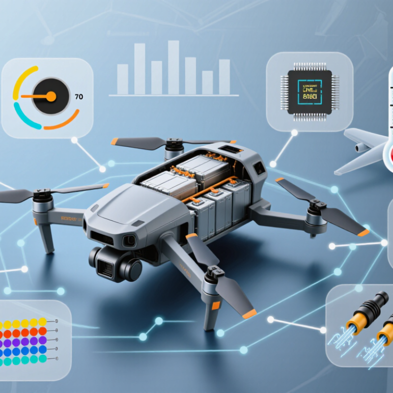
Define the UAV’s Power, Payload, and Flight Requirements
7 Tips for Choosing a Compact UAV BMS
Define the UAV’s power, payload, and flight requirements before selecting a compact BMS. Tip 1: Measure the propulsion system’s peak current during takeoff, not only its average draw. Tip 2: Add power demands from cameras, sensors, communication equipment, and flight computers. Small loads accumulate quickly. Tip 3: Record the payload weight, including cables and mounting hardware. A heavier payload increases motor demand and reduces flight time.
Tip 4: Match the battery voltage to the motors and onboard electronics. Tip 5: Estimate the required flight duration under realistic conditions, including wind, climbing, and repeated maneuvers. Laboratory figures can mislead. I once trusted an optimistic estimate and overlooked the energy used during frequent altitude changes. That mistake changed the required reserve.
Tip 6: Check whether the BMS can handle short current spikes without unnecessary shutdowns. Tip 7: Confirm its size, mass, thermal performance, balancing accuracy, and protection features. A compact BMS should fit securely without blocking airflow. Also inspect data accuracy for voltage, current, temperature, and remaining capacity. These readings support safer maintenance decisions. Flight testing should begin with a conservative payload and limited distance. Recheck the calculations after each test, because real conditions often expose assumptions that looked reasonable on paper.
7 Tips for Choosing a Compact UAV BMS - Define the UAV’s Power, Payload, and Flight Requirements
| Tip | Requirement to Define | Practical Design Data | Recommended Compact BMS Capability | Selection Check |
|---|---|---|---|---|
| 1 | Define the battery voltage | Common compact UAV battery systems use 3S to 6S lithium-ion or lithium-polymer packs, equivalent to approximately 11.1–22.2 V nominal. | Support the exact cell count and chemistry, with cell-level voltage measurement and balancing suitable for the selected pack. | Match the BMS overvoltage and undervoltage thresholds to the battery manufacturer’s specified limits. Do not select a BMS only by nominal voltage. |
| 2 | Calculate continuous and peak current | A small multirotor may draw 10–25 A continuously and 30–60 A during takeoff or rapid maneuvering, depending on motors, propellers, and payload. | Provide continuous and peak discharge ratings with short-circuit, overcurrent, and overtemperature protection. | Choose a continuous rating above the measured maximum by a practical safety margin, and verify that peak current duration is adequate for takeoff and acceleration. |
| 3 | Account for payload and mission power | Cameras, LiDAR units, communication equipment, and delivery mechanisms can add approximately 5–30 W or more to the aircraft’s electrical load. | Offer accurate current and energy monitoring, separate load output protection, and sufficient connector and conductor capacity. | Estimate total power as propulsion power plus avionics and payload power. Confirm that the BMS does not limit essential payload or flight-control loads. |
| 4 | Match capacity to required flight time | A compact UAV pack may range from 2 Ah to 10 Ah. Usable capacity is lower than rated capacity because a reserve is needed to protect the battery and allow a safe landing. | Track state of charge using coulomb counting, voltage, current, temperature, and battery history where available. | Use the estimate: flight time in hours ≈ usable battery capacity in ampere-hours ÷ average current. Include a reserve rather than planning to use 100% of rated capacity. |
| 5 | Check weight and physical integration | For compact aircraft, every additional 50–100 g can affect payload capacity, power consumption, and flight endurance. | Use a lightweight board with suitable dimensions, mounting holes, thermal paths, and low-resistance power connections. | Confirm BMS mass, enclosure size, connector orientation, cable length, and clearance from motors, propellers, and other heat sources. |
| 6 | Define operating and charging conditions | Outdoor UAVs can experience cold starts, direct sunlight, vibration, moisture, and rapid temperature changes. Lithium batteries generally require controlled charging above freezing conditions. | Include multiple temperature sensors, charge and discharge temperature limits, cell balancing, and protection against abnormal charging conditions. | Verify the BMS temperature range, sensor placement, vibration resistance, moisture protection, and compatibility with the intended charger. |
| 7 | Select telemetry and safety functions | Flight controllers benefit from battery voltage, current, state of charge, remaining capacity, temperature, cycle count, and fault information. | Provide a suitable digital communication interface, fault logging, balancing status, and configurable protection thresholds. | Confirm protocol compatibility, update and configuration access, fail-safe behavior, and the ability to trigger low-battery or emergency-landing alerts. |